Understanding Heat Pump Running Costs and Carbon Impact in AHUs
- Theme
- Manufacturing innovation
- Reading time
- 12 minutes
- Published
- By
- David Black
There is a strong emphasis on the global warming impact of refrigerants in integrated DX heat pump for Air Handling Units. But what about the units’ heat pump running costs and heat pump carbon emissions in operating such units? These operational factors play an important role in understanding the true environmental impact of these systems.

Understand the key drivers of operational performance
While refrigerant impact is often the headline topic, the true environmental footprint of an integrated DX heat pump within an Air Handling Unit depends heavily on how efficiently the entire unit operates. This includes not only the unit running costs but also the total carbon emissions generated throughout its life cycle. To really assess these impacts accurately, it is essential to look at the core operational factors that drive energy consumption.
Small changes in system design can deliver significant long-term savings
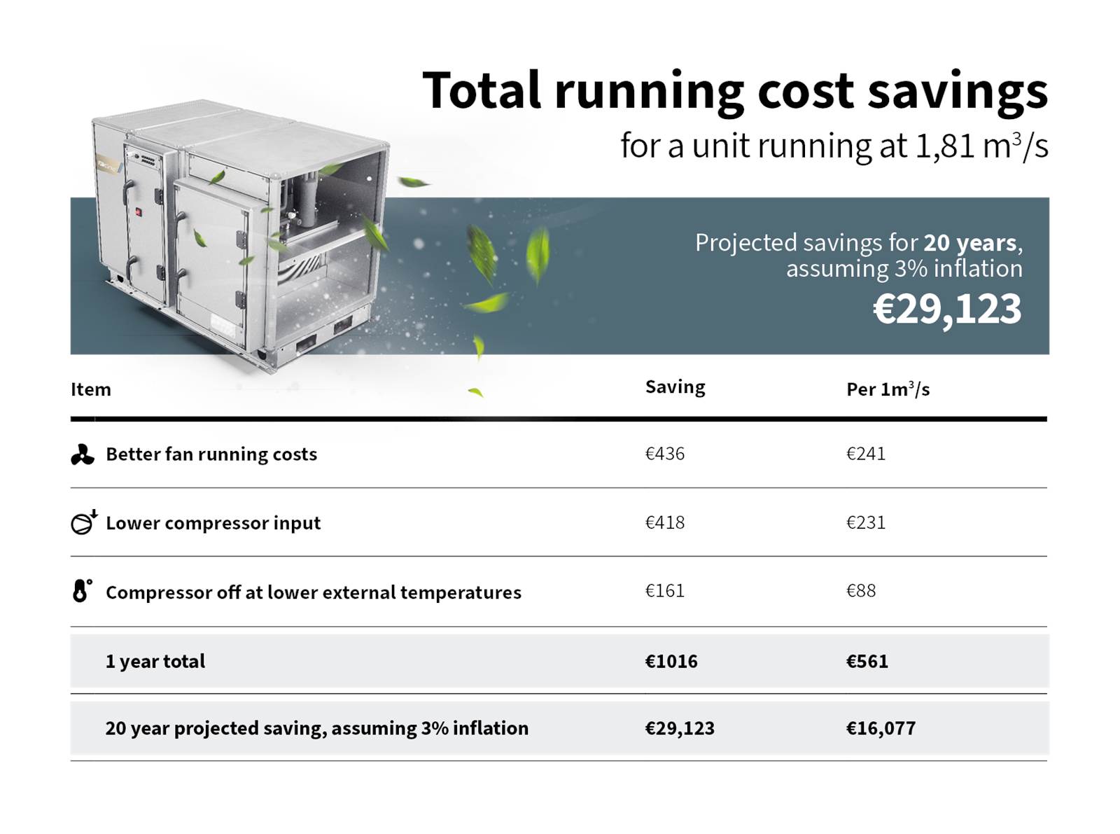
This example highlights how optimised components and smart system integration can dramatically reduce running costs—delivering over €29,000 in projected savings across a 20-year lifecycle.
While refrigerants often dominate the sustainability conversation, this clearly shows that operational performance plays an equally critical role in determining both cost and carbon impact.
To understand where these savings come from, it’s important to look at the core factors that influence system efficiency.
By contrast, cheaper solutions typically introduce unnecessary pressure drops which result in the building operator paying excessive running costs over the expected 20-year lifetime of the unit. Recent market events have shown just how costly it can be when running costs are overlooked at the design stage.
*Based on a unit in the UK ventilating commercial property during office hours amounting to 3500 hours per year.
Calculations made in FläktGroup Life Cycle Cost (LCC) software in ACON.
2. Heat Recovery Efficiency
The greater the amount of energy recovered by the heat recovery device, the less work the heat pump must do. This directly reduces the compressor input, running costs, and heat pump carbon emissions.
We understand the optimal heat recovery efficiency, and we provide our ReCooler with an optimised heat recovery efficiency of ~85%. By recovering both sensible and latent energy through the use of a high-performance sorption rotor, the heat pump operates more efficiently, requiring less electrical input. The ReCooler heat pump does the least amount of work to deliver the correct supply temperature and therefore delivers lower running costs and associated carbon emissions.
Cheaper units commonly rely on hygroscopic rotor, which recovers significantly less cooling energy. This forces the compressor to work harder, increasing the running cost and overall carbon footprint.
3. Location of the Heat Pump Circuit
There are two design approaches for incorporating DX heat pumps into an AHU
Poor design: Extract coil on the system side rotor - When an AHU mounted heat pump is in heating mode, cooling energy is rejected onto the rotor. Put another way – when you want heating you recover cooling. The result? To meet the required supply temperature the heat pump must work harder leading to increasing running costs.
Let’s consider a typical winter scenario. The external temperature is -5°c, the unit is supplying air at 20°c and the air is returning to the AHU at 20°c. With the extract coil on the system side of the rotor cooling energy is recovered and the temperature onto the heating coil is coming off the rotor at ~6°c. The heat pump is then heating from ~6°c to 20°c, that’s a temperature rise of 14°c.
FläktGroup design: Extract coil on the atmospheric side - The alternative is to have the extract coil on the atmospheric side of the rotor, now only heat energy is recovered. The compressor now only needs to raise the temperature by 3°c, resulting in up to ~80% less compressor input and lower running costs.
In summer when cooling is required the exhaust coil on a poor design rejects heat into the exhaust airstream. So, if the exhaust coil is on the system side of the rotor, heat is being recovered when cooling is required instead. This is poor design.
So, let’s consider a typical summer scenario now. The external temperature is 32°c, the unit is supplying air at 18°c and the air is returning to the AHU at 24°c. The cheap solution cannot recover any cooling energy because the extracted air is being heated by the extract coil.
FläktGroup’s solution, i.e. the ReCooler, recovers ~85% of the cooling energy. The cheap solution is cooling from 32°c down to 18°c whilst the ReCooler is cooling from ~25.5°c down to 18°c. This results in 50% less power to the compressor and therefore lower running costs and significantly reduced heat pump carbon emissions.
If the extract coil is on the atmospheric side of the rotor then the rotor can:
- Recover heat when heating is required
- Coolth when cooling is required
If the extract coil is on the system side of the rotor it:
- Recovers cooling when you want heating
- Doesn't recover any cooling when you want cooling
In conclusion, the positioning of the extract coil is not just a design preference, it is a decisive factor in achieving efficient heating and cooling performance. By placing the extract coil on the atmospheric side of the rotor, the ReCooler ensures that the heat recovery device always supports, rather than works against, the intended operating mode.
4. Compressor Input Power
Compressor power typically represents 20% of the total electrical consumption. By optimizing:
- Energy recovery
- Coil positioning
- System configuration
… the ReCooler significantly lowers the required input power, lowering both running costs and reduces associated carbon emissions across the lifecycle of the unit.