Optimising AHU Performance with Smart Design for Net Zero
- Theme
- Sustainable performance
- Reading time
- 7 minutes
- Published
- By
- David Black
In an age of climate-conscious design and rising energy costs, efficiency in HVAC systems has never been more urgent.
Why Efficiency in AHU Design matters
Efficiency in air handling systems may feel like a modern concern, but it can actually be traced as far back as the early 19th century, to the industrial revolution. This was a time where maximising airflow while minimising the use of coal was the biggest challenge. What has changed since then is the scale of buildings, the sophistication of systems, and the urgency of climate change. Optimal efficiency in AHU design is not simply just about saving money; it is about meeting global sustainability goals and regulatory standards. This includes the integration of energy recovery components to capture and reuse waste energy within a ventilation system.
Cue our Life Cycle Cost programme
FläktGroup’s Life Cycle Cost (LCC) programme can calculate kWh of power consumption, running costs and associated CO2 emissions of any AHU configured in our selection software. We can also use it to understand what the optimal heat recovery efficiency is. The performance data within that programme is audited by Eurovent. Carbon intensity of the electrical generation [3] and cost [4] have been taken from independent free access sources. This comprehensive analysis ensures that energy recovery performance is accurately factored into lifecycle assessments. See references.
Carbon Trust publication UK
The basis for this approach originates from a publication by the Carbon Trust in the UK [5], which evaluated heat recovery system (HRS) performance under UK fan coil system design conditions. It demonstrated that an HRS with 80% thermal efficiency was able to recover 100% of the energy available for recovery – achieving what the report defined as an Annual Energy Efficiency (AEE) of 100%. In other words, under typical UK conditions, an 80% efficient heat exchanger captures all the practically recoverable energy from the exhaust air. It highlights how well-calibrated energy recovery can capture all useful thermal energy in a real-world application.
Pursuing higher HRS efficiency beyond this point can be counterproductive. While the thermal recovery might increase, the associated higher pressure drops leading to increased fan consumption, which outweighs any marginal gains in heat recovery. Therefore, for typical UK climates and systems, an 80% efficient HRS represents the optimal balance between energy recovered and additional system energy use.
Confirming the Carbon trust analysis
Assuming a supply temperature of 17°c, an extract temperature of 23°c and heat pick up of 1°c from the fan result is a heating coil load of zero. This should result in a heating coil dimensioned with an acceptable safety margin but of reduced capacity. A smaller heating coil will have less air pressure drop and deliver lower specific fan power. When properly implemented, energy recovery systems reduce the load on heating coils and therefore improve overall efficiency.
Having confirmed the basic principle demonstrated by the Carbon Trust – that an 80% efficient heat recovery system (HRS) can recover 100% of the energy that is available to be recovered under UK design conditions – we can begin to define what “optimal efficiency” in AHU design mean. However, it’s important to understand that the goal is not to reach 100% device efficiency, but instead to achieve the best overall system performance for the specific project.
To configure an AHU for optimal energy performance, several factors must be carefully evaluated:
- Geographic location, as outdoor air temperatures and humidity levels vary across regions.
- System design, since different ventilation strategies (e.g., displacement ventilation vs. fan coil units) require different supply air temperatures and airflow rates.
- Local energy costs and the carbon intensity of the electrical grid, which affect both the economic and environmental impact of running the system.
It's also essential to distinguish between the efficiency of the heat recovery device itself and the Annual Energy Efficiency (AEE) of the AHU. The Carbon Trust example illustrates that, in a well-designed system, an 80% efficient heat recovery unit can achieve an AEE of 100% — meaning it captures all the energy that can practically be recovered under typical conditions. Attempting to push beyond this by using a higher-efficiency device may increase pressure drops, which in turn raises fan energy consumption and can lead to diminishing or even negative returns in overall system efficiency.
LCC Analysis for AHU Performance and Efficiency
For consultants tasked with specifying AHUs that balance energy performance, carbon targets, and lifecycle cost, data driven tools are essential. LCC analysis helps by simulating real-world performance based on project-specific factors such as climate conditions, air temperatures, operational schedules, and local energy costs. The charts below illustrate typical LCC inputs and outputs, helping consultants validate design choices with clear metrics for energy demand, cost, and CO2 impact. Energy recovery modelling plays a vital role in these simulations, influencing both environmental and financial outcomes.
Chart 1: Input Configuration – LCC Setup Parameters
This form captures all the critical project-specific inputs – including climate zone, air temperatures, operating hours, and local energy costs – that form the basis of AHU performance simulation. It then produces comprehensive data as shown in the diagram below, demonstrating that energy recovery efficiency must align with local climate and system design to be effective.
Chart 2: Energy Diagram – Annual Energy Demand Profile
This graph visually displays the AHU’s annual thermal performance, breaking down heating, cooling, and heat recovery demands over the course of a year.
Chart 3: Energy Calculation – AHU Performance Summary
This output sheet summarises the simulated AHU’s energy efficiency, fan power, and annual operating costs, enabling direct comparison of energy use and CO2 emissions across system components.
Using these tools we have analysed many locations in Europe and compared two energy efficiencies. A comparison table is shown below but this is for one set of supply and extract conditions. As these criteria change from project to project and location, the best solution should always be evaluated to minimise energy consumption.
This chart shows that for all locations highlighted in green it is better to have an 81% heat recovery than 85%. The colder the city, the higher the heat recovery efficiency should be.
Other design considerations
Cooling recovery should be considered when configuring AHU cooling coils. However, too high efficiency increases pressure drop – which increases fan power – while only marginally improved cooling. Typically (per m³s) a cooling recovery of 85% reduces the cooling coil air pressure drop by <5 pa. compared to a cooling recovery figure of 80% whilst increasing the HRS air pressure drop by 80 pa. Optimising energy recovery for both heating and cooling requires careful balancing to avoid inefficiencies.
Fans in AHUs are typically dimensioned to minimise specific fan power (SFP) at the maximum design airflow. SFP is a key efficiency metric, defined as the amount of electrical power (in kW) required to move a unit volume of air (in m³s). Lower SFP means higher fan efficiency and reduced energy consumption.
In VAV applications the greater the airflow turndown the more the fan moves away from the point of maximum efficiency. Fig 5. Below shows the impact on AHU SFP at full, 75% and 50% airflow.
Table: AHU SFP for VAV applications
This table shows the SFP values for an AHU in a VAV system under different fan configurations and airflow conditions. For a unit normally running at 50% of the maximum design airflow a reduction of 25% in running costs is achievable with the correctly dimensioned fans. These also have a lower purchase cost.
Conclusions
Proper sizing of heat recovery, heating, and cooling coils is key to lowering AHU carbon emissions and cutting operating costs for building owners. Integrating energy recovery into these design choices helps unlock further savings and emission reductions.
For VAV systems, carefully considering anticipated actual operating airflows rather than maximum airflows can further improve energy efficiency.
Given the almost infinite number of possible AHU requirements, it is extremely difficult for designers to make informed decisions on the best solution for both the client and the environment. Responsible AHU manufacturers should be able to advise designers on the optimal answer to their problem. The best way to prove this is by utilizing a well-designed LCC programme which provides data for kWh of power consumption, running costs and associated carbon emissions. This ultimately ensures energy recovery strategies are grounded in real-world data.
What exactly is Optimal Efficiency?
There is no simple answer to this question because true optimal efficiency depends on many different factors as discussed. It all depends on the specific needs of a building and its system, which is going to vary. However, the underlying principle is clear, optimal efficiency means achieving the lowest energy use and carbon emissions for the required performance. It means sizing coils correctly, configuring the design for realistic airflow rates, and selecting the correct equipment based on operating conditions.
Consultants need to consider this challenge when selecting a responsible AHU manufacturer. By partnering with FläktGroup we utilize robust Life Cycle Cost (LCC) analysis tools that can make decisions based on real data. That includes energy use (kWh), running costs, and associated carbon emissions across a system’s lifespan.
Whenever you are selecting or specifying AHUs, it is always good practice to insist on a full LCC analysis early in the design process. This ensures you aren’t just meeting today’s project goals – you’re also safeguarding the building’s operational future, cutting long-term costs, and helping achieve sustainability targets. Energy recovery, when used intelligently, becomes central to delivering these long-term performance outcomes.
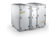
Explore our complete AHU range
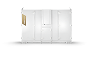
Compact Air Handling Units
Ideal for applications where space is limited but performance cannot be compromised. These units offer a compact footprint with high efficiency and are perfect for plant rooms or technical spaces.
-
 COM4plus AIR HANDLING UNIT
- High performance solution with rotor
- Plate heat exchanger solution for heating
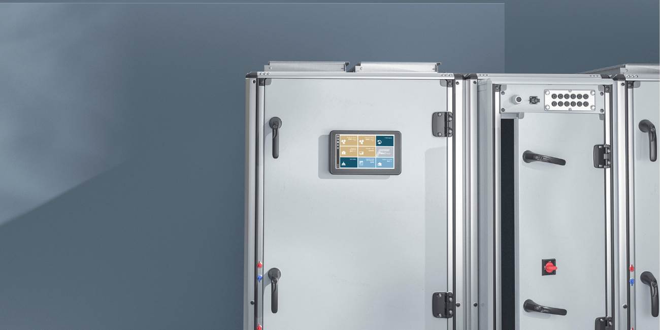
- Plug n' play design with webserver and BMS connection
- Integrated electrical cabinet with ISYteq 4.0
- T2/TB2/L1/D1 Eurovent certified casing
-
 eQ PRIME SIDE AIR HANDLING UNIT
- Energy efficient components and integrated controls
- Plug and Play installation
- Short Delivery time
- Connected
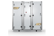
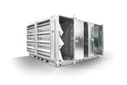
Modular Air Handling Units
Our most flexible and scalable solution. Modular AHUs like CAIRplus are engineered for complex projects with high airflow demands, advanced energy recovery, and full integration with BMS and cloud-based control systems.
-
 CAIRplus Air Handling Unit
- Fast and easy installation – smartly designed block joints, cable connections, and lifting details save time and reduce installation costs
- Reliable integrated controls – factory-fitted, fully tested controls ensure trouble-free commissioning and minimise installation cost and setup time (as little as 4 hours)
- Hygienic and safe – designed according to VDI 6022 with flat, cleanable inner surfaces and easy access for component replacement
- World-class efficiency – low SFP values allow selection of smaller units for reduced energy consumption
- Maximised ROI – optimal energy recovery and low operating costs maximise return on investment
- Flexible and tailored – adaptable to any environment for cost, energy, space, and time savings.
-
 eQ MASTER® AIR HANDLING UNIT
- Tailor made for customer needs
- Energy Efficient and optimized with integrated control
- Large variety of high efficiency components
-
 eQL® AIR HANDLING UNIT
- High degree of flexibility of functionality, configuration and materials
- Flexible and high efficiency energy recovery systems
- Optional service corridor
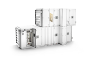
Top Connected Air Handling Units
Perfect for low to medium airflow needs in offices, schools, or residential buildings. These units are installed in ceiling voids with all connections accessible from the top—making them ideal for fast installation and easy maintenance in confined spaces.
-
 COM4top AIR HANDLING UNIT
- High performance solution with 2-step heat recovery system via a double heat plate exchanger for heating
- Web server and a BMS connection
- Duct connection from the top
- Integrated electrical cabinet
- T2/TB2/L1/D1 Eurovent certified casing
-
 eQ PRIME TOP AIR HANDLING UNIT
- Energy efficient rotary heat exchanger
- Plug and Play installation
- Easy maintenance with front doors
- Connected