


MOTORS BASIC. PART ONE: BASIC PRINCIPLES – ELECTRICAL PRINCIPLES, SIMPLE MOTOR OPERATION, ALTERNATING CURRENT; AND TRANSMITTING THE ELECTRICITY
Understanding the basics of electric motors is vital to be able to select the right motor for the right application. In this article we look at the principles of DC and AC electricity and simple motor operation.

Electrical Principles
At its most basic, electricity can be defined as the flow of an electrical charge. In its simplest form, a direct current (DC) circuit consists of an electrical source with a conducting wire connected between one of the source terminals and an electrical device, and another conducting wire connected back from the device to the other source terminal.
Perhaps the simplest such DC circuit would be a battery connected to a light bulb. Charge flows from one battery terminal, passing through the lightbulb (and making it light up) and then returning to the other battery terminal. If the circuit is broken, the flow stops, and the bulb no longer glows.
That flow of electricity is referred to as electrical current, and that current – the amount of charge flowing through a component in unit time – is measured in Amps (Amperes in full, SI symbol A). The resistance in the circuit – what could be thought of as the electrical friction – is measured in Ohms (SI symbol Ω).
The voltage, also known as the potential difference, is the pressure that drives the current through the circuit, and is measured in Volts (SI symbol V). As per Ohm’s law, the voltage in Volts is always the product of the current in Amps and the resistance in Ohms.
The power, or the rate at which electric energy is transferred, is measured in Watts (SI symbol W), and is calculated by multiplying the voltage in Volts by the current in Amps.
Therefore, there are two key equations:
- Voltage = Current x Resistance
- Power = Voltage x Current
A basic electromagnet is an important part of understanding how any motor works. When any electrical current flows through a wire, a weak magnetic field is produced. The strength of the magnetic field can be increased by coiling the wire around an iron core, as illustrated in Figure 1. The strength of the magnetic field can also be increased by having more coils, as well as by increasing the electrical current.
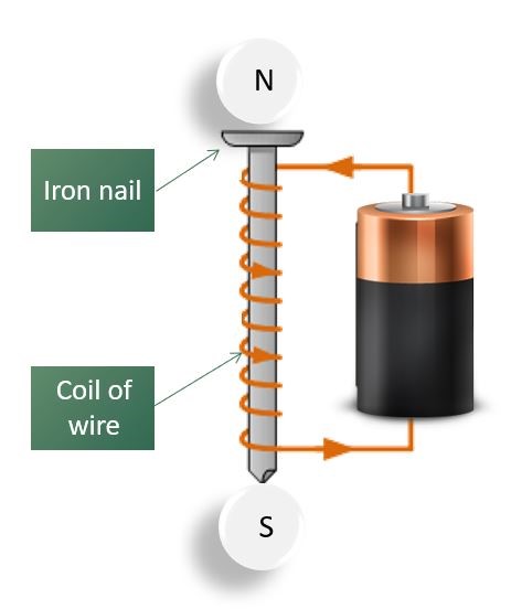
Figure One: A basic electromagnet
Simple Motor Operation
Figure 2 shows the simplest type of DC motor, which is constructed from a coil of wire located on a pivot so that it can rotate. The two ends of the coil are connected to two halves of a ring, called a commutator, which also rotates with the coil. The commutator is connected to a power source (in this case a battery) via brushes, which allow electrical current to flow to the commutator as it rotates.
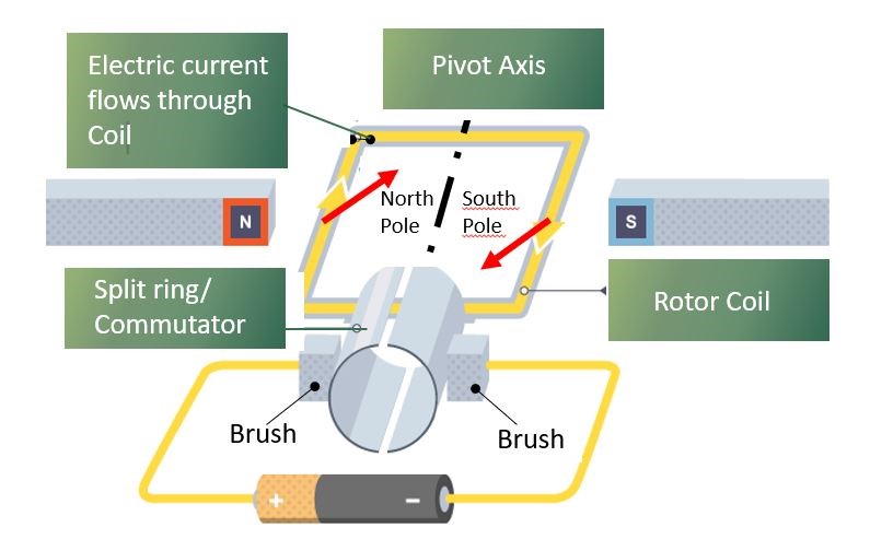
Figure Two: A simple DC motor
When electrical current flows through the rotor coil, a magnetic field is generated, resulting in a north and south magnetic pole forming on opposite sides of the coil. Meanwhile, two fixed magnets are positioned close to the sides of the rotor coil, with their poles opposing the magnetic poles induced in the rotor coil, which means that the poles in the rotor will be repelled by the fixed magnets.
This repulsion will make the rotor start to turn on its axis. All other things being equal, the rotor would turn 180 degrees and then stop turning when the rotor poles arrived alongside the opposite magnetic poles of the fixed magnets, due to magnetic attraction.
However, because of the commutator and brushes arrangement, as the rotor coil rotates, the ends of the coil become connected to the opposite terminals of the battery, and the current flowing through the rotor coil changes direction and the sides of the coil swap polarity. As a result, once again the coil and the fixed magnet poles repel each other, and the rotor keeps turning on its axis.
The momentum of the rotating coil pushes the poles past each other, and so the rotor continues to turn, driven by the repelling fixed magnets.
Alternating Current
Because it is easier and cheaper to generate and, importantly, transmit, the electricity we receive through grid supply systems is in the form of alternating current (AC).
Unlike DC, where the voltage is continuous, an AC waveform sees the voltage change with time, alternating between a positive value and a negative value. One complete cycle consists of the voltage changing from zero to maximum to zero to minimum and then back to zero; the number of such cycles per second is known as the frequency, and this is measured in Hertz (SI symbol Hz). For almost all electrical supplies around the world the frequency is either 50Hz or 60Hz.
Domestic electricity supplies have just one phase – in other words, a single waveform, whereas most AC supplies used in industrial applications are 3-Phase, using the waveforms shown in Figure 3. As a result, unlike domestic cabling which has just three wires (live, neutral and earth), 3-Phase supplies have four or five wires (U, V and W, earth and sometimes neutral).
Note that the 3-Phase electric motors offered by Fläkt Woods do not need a neutral connection because they have three balanced windings.
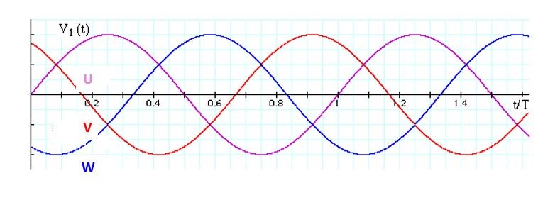
Figure Three: A 3-Phase alternating current waveform
Transmitting The Electricity
Given that Power = Voltage x Current, then for any given power level, the higher the voltage, the lower the current. This is important, because if an overhead line carries a large amount of current, then it heats up and energy is wasted. So if electricity is transmitted at a very high voltage, the current needed to transfer the same amount of energy is much lower, resulting in less heat and a more efficient transfer.
For this reason, step-up transformers boost the voltage from the 25kV generated in power stations to (typically) 400kV – for transmission over longer distances, transmission cables (which consist of the three phases plus neutral) can carry up to 765kV, and in some cases even higher voltages.
Obviously such high voltages are not suitable for either industrial or domestic use, so the voltage is reduced by step down transformers in various substations close to where the electricity will be used. Substations step down the power to produce high voltage (typically 11kV), medium voltage (typically 6.6kV) or low voltage (typically 400V), ready to be consumed by a number of industrial applications such as factories, hospitals or railways.
Where a single phase supply is required (mainly for domestic use), one of the three phases and the neutral line are used from a low voltage supply. Electricity companies will balance a number of homes across each of the three phases, helping to balance the load on the cables.
The earth connection is created by driving a copper stake into the ground (hence ‘earth’), and is used as a low resistance path for any electrical surge that would be created by an electrical fault.
Recently viewed products
-
SANDWICH PANELS
Clean Room Building Elements
-
Aria-DENCO® Fan Wall Unit
Data Centre Air Handling Units